 Sales: 84270 07400 Email us: sales@3dwds.in
|
Sales: 84270 07400 Email us: sales@3dwds.in
|  Support: 84270 07401 Email us: support@3dwds.in
Sales: 84270 07400 Email us: sales@3dwds.in
| Support: 84270 07401 Email us: support@3dwds.in
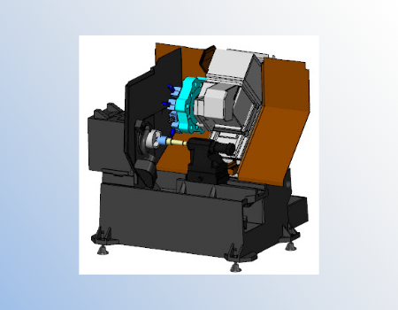
The new BobCAM for SOLIDWORKS™ Mill Turn software is a complete multitask CAM add-on that combines all of the powerful CNC programming functionality of both mill and lathe into a single streamlined C axis machining solution. BobCAM for SOLIDWORKS™ multitask CNC software delivers high performance features in an easy to use interface designed to meet the complex programming demands of mill turn machining.
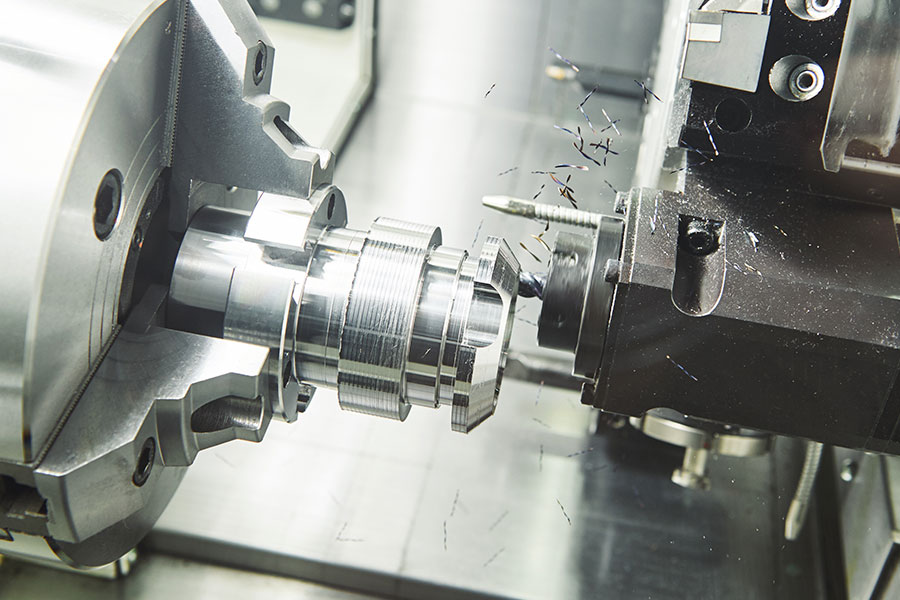
BobCAM for SOLIDWORKS™ Mill Turn, a Gold Partner CAM solution, can perform everything from simple 2 axis turning to 3 & 4 axis milling and full 4 & 5 axis simultaneous machining right inside of SOLIDWORKS™. It offers a variety of sophisticated and fully associative machining strategies within an intuitively designed wizard driven interface. BobCAM for SOLIDWORKS™ gives you the control needed to easily program non-perpendicular multiaxis tool movements involved in machining intricate features and compound angles. This is particularly useful for programming complex parts such as medical components, complex valves, tool holders, oil drilling tools, and many others.
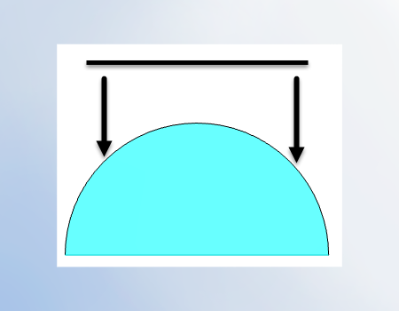
Multiple turning cycles to rough & finish your parts with options that go beyond traditional canned cycles commonly available on cnc controls. Advance features that minimize geometry editing, limit and control toolpath.
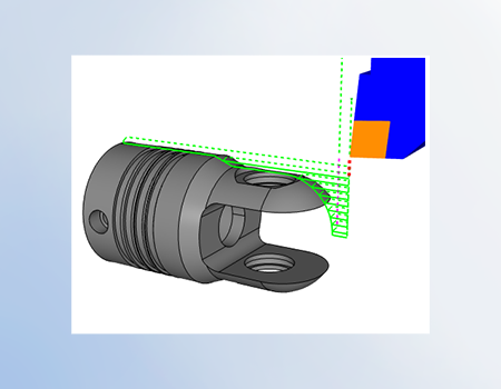
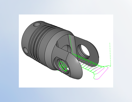
Program machining features on the end of your part like you would with a typical milling center. Drill, Tap, Profile, Pocket, Engrave, Edge break and more. Use long code , Y Axis or polar to match the code output that’s optimal for the operation and control capabilities.
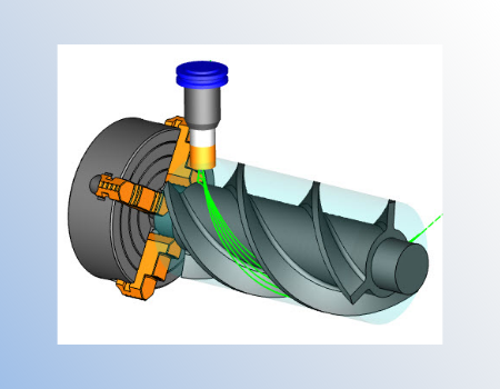
Machine features into the outside diameter of your parts using wrapping groups. Programming with the C axis your tool will be pointed to the axis of rotation. Great for engraving, pockets, slots and more.
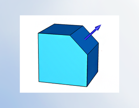
Use index systems to align tool orientation ( clock the part ) for your Y axis programming. Once an index system is established you can use both 2D and 3D toolpath machining features.
Expand your capabilities beyond on board programming cycles when utilizing the full suite of toolpath operations available. Complete 2D and 3D toolpath strategies for roughing, semi finishing and finishing using the same workflow as traditional milling.
Advanced simultaneous cutting strategies for expert programming of Multi-task / Milling Head configured machines. Program complex models that require True 4 or 5 Axis. Control tool tilt, run of the tool, angle range limits and more.
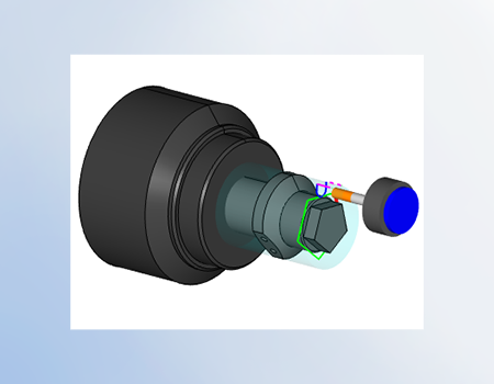
Programming on your main or sub-spindle with your upper or lower turret using BobCAD's submachine / work-groups. Supporting up to 10 spindles and 10 turrets.
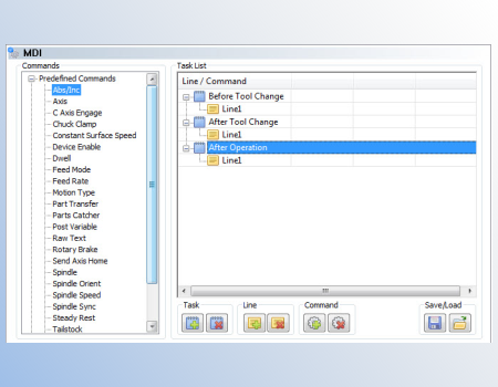
Why edit your g-code programs after posting to insert special blocks of code when you can use MDI right within the toolpath wizard? Users can add custom or saved blocks of code before & after tool changes or at the end of operations. Used to control turret location, part catchers, steady rests, part transfers and other auxiliary functions.
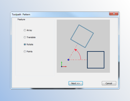
Reduce your programming time by creating patterns. Allows users to shortcut programming by making copies of machining features where multiple instances occur.
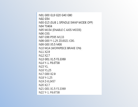
Mill Turn packages require machine specific post processors. Our posting team will build you a custom post processor based supplied samples and machine kinematics. Special functionality can be added using the post processors API, developed in-house or through BobCAD’s posting services.
Display your tool and holder as you step through or play your toolpath operation. Rapid graphical feedback for direction of cut, tool hangout, sequence, cutter location, tool orientation and more.
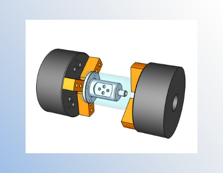
Use 3D models to display a “virtual machine” and its components in simulation. Reduce setup time and programming errors by detecting collisions, over travels and more. Find and resolve issues before you ever get out to the machine.
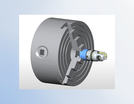
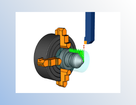
Chuck configuration is now available where users can define the chuck and jaws by input or STL files. Jaws will open and close on your part / stock geometry. Visually check chuck jaws for collisions, spinning or if they are properly clocked for part transfers.
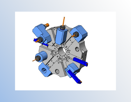
The Mill Turn tool crib is used to establish, modify and configure your turret with tools, holders, adapters and their mounting orientation. Quickly rearrange configurations by unmounting or moving tool assemblies from one station to another. Use the shelf to store commonly used tools that are not currently in use. Save complete turret configurations for future projects.
GENERAL
TURNING TOOLPATHS
2.5 Axis
3 Axis
4 Axis
5 Axis
Surface Based Toolpath (3, 4, & 5 Axis Output)
In order to use BobCAM for SOLIDWORKS™, you must have SOLIDWORKS™ 2014 or later installed on the same computer that you choose to install BobCAM for SOLIDWORKS™. The following are system requirements for using Windows Vista, Windows 7,Windows 8 or Windows 10 x64.
Recommended System Requirements:
Minimum System Requirements:
When using physical media (disk) to install the BobCAM software, the optical drive being used must support DVD-ROM disks. The system requirements listed above are suggested for running the BobCAM for SOLIDWORKS™ add-in. Please adhere to the system requirements listed inside SOLIDWORKS™ for optimum performance within the SOLIDWORKS™ system.


Our solutions enable you and your team to quickly transform new ideas into great products.
Ready To Buy Request for Demo Whatsapp Free Trial Call Us Email Us
Sales: 8427007400 / Email: sales@3dwds.in
Support: 8427007401 / Email: support@3dwds.in
Punjab, Ambala, Delhi, Jammu & Kashmir, Himachal Pradesh
SCF 26, Phase 2, Urban Estate,
Focal Point, Ludhiana - 141010, (Punjab) India