 Sales: 84270 07400 Email us: sales@3dwds.in
|
Sales: 84270 07400 Email us: sales@3dwds.in
|  Support: 84270 07401 Email us: support@3dwds.in
Sales: 84270 07400 Email us: sales@3dwds.in
| Support: 84270 07401 Email us: support@3dwds.in
BobCAM for SOLIDWORKS™ software for 2 axis lathe and turning centers makes it easy to set advanced 2 axis toolpaths for OD and ID roughing, finishing, threading, grooving, boring, drilling, and cut offs. This powerful CAM programming software is a complete CNC lathe solution for all of your simple and complex part turning jobs.
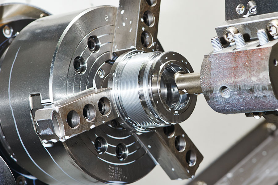
The new BobCAM for SOLIDWORKS™ Lathe Gold Partner CAM solution allows you to apply powerful toolpath operations to your part models right inside of SOLIDWORKS™. Using an intuitive wizard driven interface, you’re able to quickly set up 2 axis machining operations for maximum programming efficiency. Applying multiple machining strategies to a single model feature is made easy with Dynamic Machining Strategies™. You also have access to a realistic machine simulation right inside of BobCAM for SOLIDWORKS™ that allows you to test and confirm your programming before ever cutting a chip.

Easily define where on your part geometry you want toolpath created using the feature type programming drop-down. Pick from OD, ID, Front Face & Back Face. Control right to left or left to right cutting based on region selection.
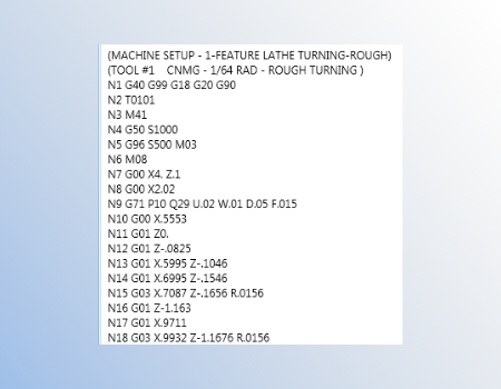
Utilize your machine's canned cycles for short, efficient programs that are easy to edit at the control. Separate moves are available for those machines without canned cycle or when using BobCAD specific cycles.
Used as boundary to limit toolpath created on the Face, OD, ID or Back side of the part. Choose From Stock, From Geometry or Custom to dial in and restrict toolpath to desired areas.
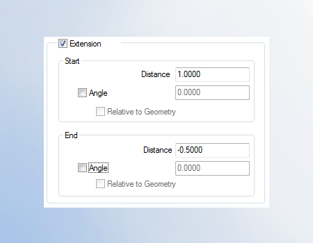
Stop editing geometry to trim back or extend out your toolpath. Using extensions users can enter a positive value to extend or negative value to trim back their toolpath. Independent control for the start and end of cut with optional angle extension.
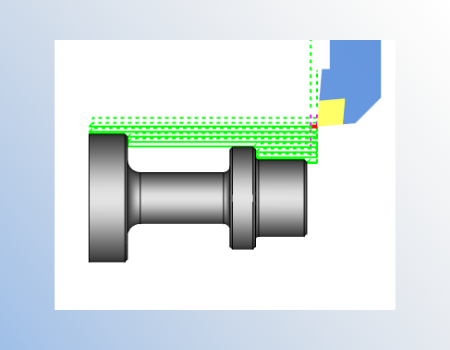
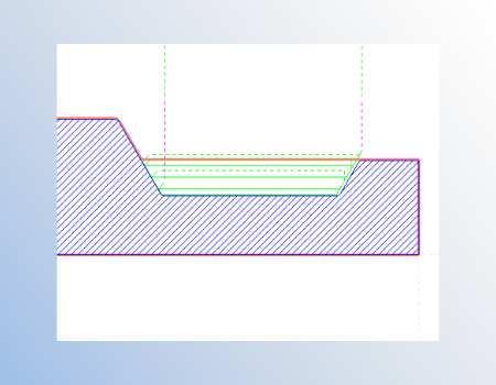
Jump over grooves and undercuts without editing your geometry. This feature parameter can be turned on at any time to prevent undercuts found parallel to the X or Z axis. Providing faster programming while reducing geometry editing.
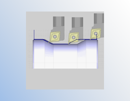
Avoid violating your geometry features with tool holder or insert geometry. This compensation option ensure collision-free programming for V groves and other part features where standard inserts and holders could gouge your part.
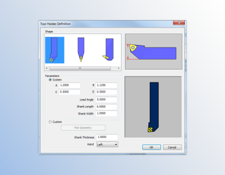
Quickly set up holders for right or left hand, neutral and back turning. Choose from the default holder shapes and enter sizes that define the holders.
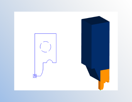
Users can draw their own inserts and holder profiles to match non-standard tooling. Custom shapes allow with gouge checking and undercutting compensation.
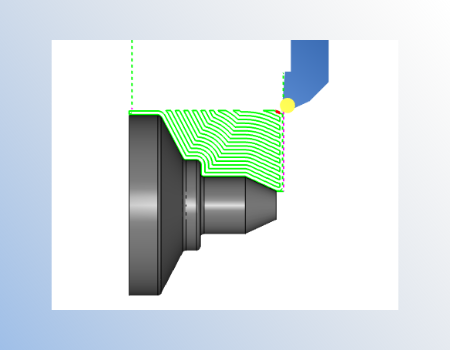
Roughing patterns that go beyond standard canned cycles. Allowing for offset patterns, bi-direction cutting and semi finishing. Define and use custom stock profiles to limit your toolpath, great for castings and in process stock profiles.
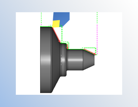
Finishing patterns that go beyond standard canned cycles. Allowing for continuous cutting, face cutting ( down cutting ) , diameter cutting ( shoulders ) and hybrid ( both). Use the custom overlap value to ensure no stock is left behind.
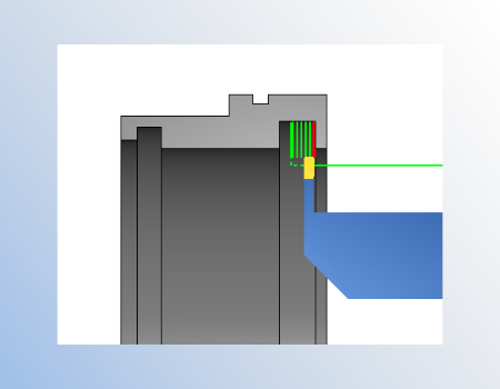
Grooving patterns that go beyond standard canned cycles. Allowing for Standard, Single-pass or Zig-Zag cutting. Advanced sorting options work from the center our, alternate steps and skip, accommodating for diverse material and tooling. Force down cutting for finishes collision checking and more!
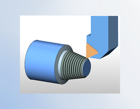
Create thread on the OD, ID, Front Face and Back face of your parts. Supporting G32, G76 equivalent for straight or tapered threads. Acme, American National, British Standard Whitworth, Buttress, Metric, Sharep V, Square, Unified National.
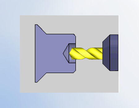
Spot, Drill, Chamfer, Bore and Ream holes on your cnc lathe using BobCAD’s hole making wizard. Pick your depth and use the wizard to setup and define your operation, tool and settings. Create your custom templates to fast track future hole cycles.
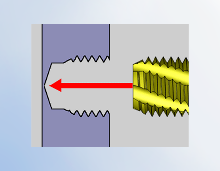
Use the thread library to pick and call tap sizes, settings and tools. Utilizing the same workflow as the hole making wizard, users can quickly add multiple tools and operations to spot, drill ,tap holes on center line.
GENERAL
TURNING TOOLPATHS
In order to use BobCAM for SOLIDWORKS™, you must have SOLIDWORKS™ 2014 or later installed on the same computer that you choose to install BobCAM for SOLIDWORKS™. The following are system requirements for using Windows Vista, Windows 7,Windows 8 or Windows 10 x64.
Recommended System Requirements:
Minimum System Requirements:
When using physical media (disk) to install the BobCAM software, the optical drive being used must support DVD-ROM disks. The system requirements listed above are suggested for running the BobCAM for SOLIDWORKS™ add-in. Please adhere to the system requirements listed inside SOLIDWORKS™ for optimum performance within the SOLIDWORKS™ system.


Our solutions enable you and your team to quickly transform new ideas into great products.
Ready To Buy Request for Demo Whatsapp Free Trial Call Us Email Us
Sales: 8427007400 / Email: sales@3dwds.in
Support: 8427007401 / Email: support@3dwds.in
Punjab, Ambala, Delhi, Jammu & Kashmir, Himachal Pradesh
SCF 26, Phase 2, Urban Estate,
Focal Point, Ludhiana - 141010, (Punjab) India