 Sales: 84270 07400 Email us: sales@3dwds.in
|
Sales: 84270 07400 Email us: sales@3dwds.in
|  Support: 84270 07401 Email us: support@3dwds.in
Sales: 84270 07400 Email us: sales@3dwds.in
| Support: 84270 07401 Email us: support@3dwds.in
Precision, Power and Performance
BobCAM for SOLIDWORKS supports better collaboration between engineering and manufacturing.
2-5 Multi Axis Milling, Lathe / Mill Turn, Wire EDM, BobART
The new BobCAM for SOLIDWORKS V10 has a ton of new features and even enhancements to existing features! With the introduction of our Wire EDM module, we’re finally able to welcome our wire-friends to the BobCAM family. Craft your art projects more easily with the redefined workflow of the all new BobART user interface!
For those requesting more control of the operation posting order, including how toolpath patterns are posted, we decided to completely rethink this portion of the software and are introducing the new Operation Tree and Tool Tree to give you all the power and control you need. Oh, and we’ve got Finishing Spring Passes, brand new Leads with point picking and automatic lead from center options, and new features and enhancements in 2, 3, 4, and 5 Axis.
BobCAD-CAM has been a SOLIDWORKS software partner since 2006 and currently support SOLIDWORKS versions 2017 to the latest 2022 version. Our CAM integration is a direct add-in within SOLIDWORKS, which reduces data translation errors from design to manufacture.
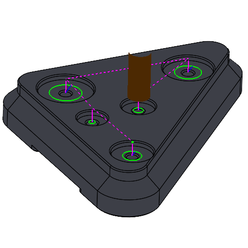
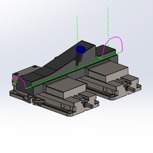
By default the Lead from Center option allows you to utilize the center most positions of the created toolpath chains. In the past, creating leads that started/ended in the center of the chain could be a little more challenging than you would initially think. In fact, customers requesting the ability to do this easily is what led to these new lead types. No need to measure areas and calculate leads as these leads work on any shape to find the center-most point created by the chains.
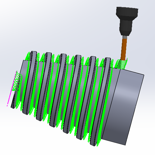
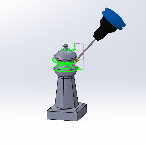
When we came out with our 4 Axis Advanced Rough and 4 Axis Advanced Finish operations, it helped a lot in the machining of those shapes, but the toolpath wasn’t specialized for those shapes and there were still some drawbacks. Everything from the step downs to the limits is designed for cylindrical shapes. That meant conical floors would have steps and air cutting on the smaller end was impossible to remove with radial limits. These issues are now a thing of the past with the new Conical Machining option. Simply select the check box on the Patterns page, set the Cone Angle and now the entire toolpath is designed for that exact shape.
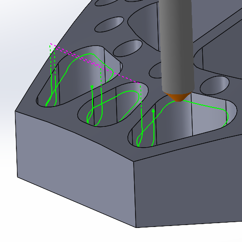
While the Deburring operation has always offered ways to specify the area to focus on by allowing selection of specific edges, check surfaces to avoid, and limiting the area by height, deburring only specific areas meant a lot of geometry selections and even adjustment of the operation settings. Now, hitting exactly what needs to be hit has never been easier. Simply select a solid, or solids from the graphics area and only the area inside of these solids will have the Deburring toolpath applied.
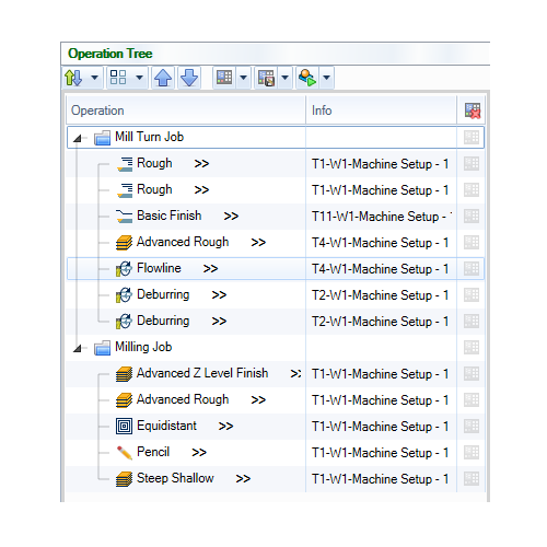
The Machining order dialog has been replaced by a complete Operation Tree which enhances the workflow in the software in many ways that were never possible. Once you’ve created your jobs in the CAM Tree, open the Tool Tree to see all your jobs, the tools in their tool crib, and which operations are assigned to each tool. For the first time ever, Mill and Lathe jobs also support MDI, or manual data input, which allows you to manually define machine movement as needed for your machining operations.
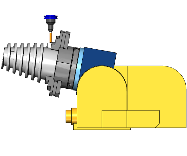
Another tilting option is added to the arsenal of the Surface toolpath types with the new Tilted with fixed angle to surface normal option. The proper tool tilt is important in multi-axis machining, and while we have many options to choose from, including staying fixed to the surface normal, in the past you have not be able to adjust the tilt based on the surface normal. In this version though, you can simply select the option, choose your reference surface and set your angles.
The Undercut option in the Options page of the Advanced Z Level Finish now allows you to do undercutting when the operation is set to 5 Axis in the Tool Axis Control page. While the undercutting option has been a huge help when using undercutting tools in a 3 Axis operation, the undercut option has so far been unavailable when setting the operation to 5 Axis. Now, when set to 5 Axis, you can use Undercut with spherical tools by simply selecting one of the Checks on the Gouge Check page, and setting the Strategy to Tilt tool. You can even set an Extend undercut area value to have full control over exactly how much is machined.


Our solutions enable you and your team to quickly transform new ideas into great products.
Ready To Buy Request for Demo Whatsapp Free Trial Call Us Email Us
Sales: 8427007400 / Email: sales@3dwds.in
Support: 8427007401 / Email: support@3dwds.in
Punjab, Ambala, Delhi, Jammu & Kashmir, Himachal Pradesh
SCF 26, Phase 2, Urban Estate,
Focal Point, Ludhiana - 141010, (Punjab) India