 Sales: 84270 07400 Email us: sales@3dwds.in
|
Sales: 84270 07400 Email us: sales@3dwds.in
|  Support: 84270 07401 Email us: support@3dwds.in
Sales: 84270 07400 Email us: sales@3dwds.in
| Support: 84270 07401 Email us: support@3dwds.in
Use state-of-the-art toolpath verification technology to simulate your virtual machine setup. Graphically check for collisions and over travels of your toolpath, tool and holder, fixture, workpiece and machine components. Gain peace of mind as you step through programs and watch simulations of your virtual setup. Get critical feedback to fine tune your setup and toolpath for error free programming.
Solid simulation comes standard with optional machine simulation to add machine components to the gouge checking process. Users can back backplot toolpaths and run solid simulations showing material removal while checking for gouges. Spend less time editing your toolpaths setting or g-code programs by running and analyzing solid simulations of your toolpath, setup and machine components.
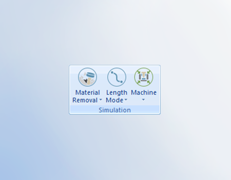
Select from multiple simulation modes to view and inspect your toolpaths and setup. Choose from: Material removal, Backplot, NC mode, Time mode , Length mode, Machine focus, Tool focus, Workpiece and stock focus.
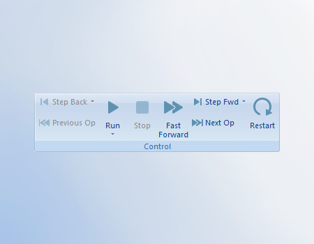
Play your toolpath simulation with the same controls as watching a DVD movie. Run, Stop, Fast Forward, step forward, Jump to the next operation, Step back, Jump to previous operation and restart; putting you in full control of your toolpath and machine simulations.
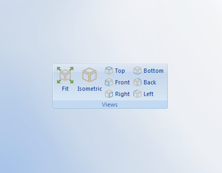
Choose from one of the standard view options to change your perspective of the simulation. Use hotkeys to jump to standard view without clicking an icon.
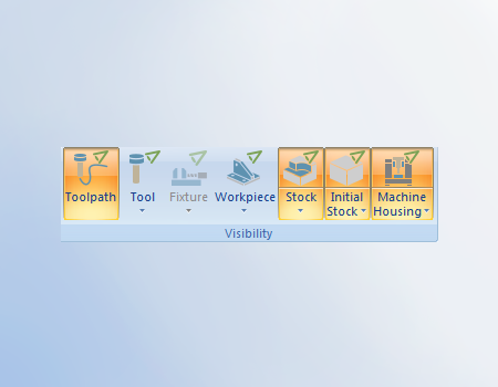
Control the display of simulation components. Toggle on and off toolpath, tool, fixture, workpiece, stock, initial stock and machine housing. Show, opaque, transparent and hide options allowing users to fully customize what they display and in what form.
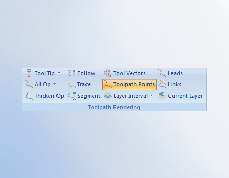
Multiple display options for toolpath: Tool tip, All ops, Thicken op, Follow, Trace, Segment, Tool vectors, Toolpath points. Layer interval and more.
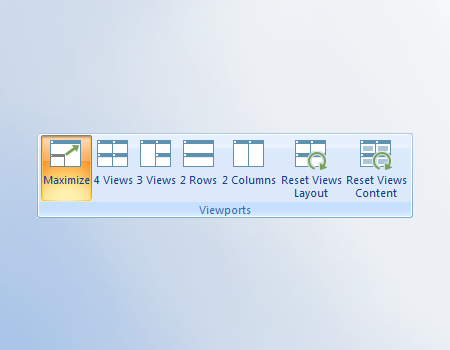
Customize your simulation experience by adjusting the number of viewports displayed. Allowing users to view their simulation from multiple perspectives within the simulation window.
Toggle on and off the measure grid to aid in measurement of machine, setup and toolpath.
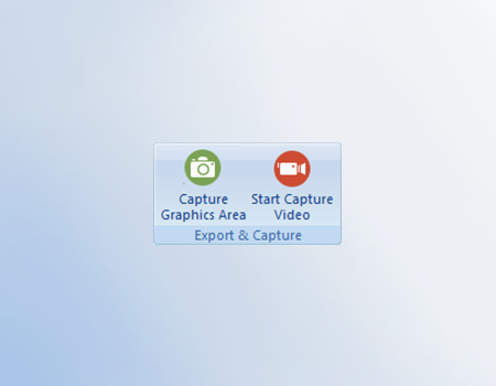
Communicate better with internal staff or external customers by capturing images and video of toolpath, setups and machine movements.
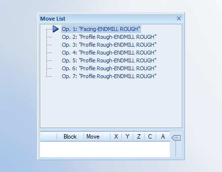
Lists the operations that will be simulated. Jump to toolpaths you want to focus on by clicking on an operation in the move list.
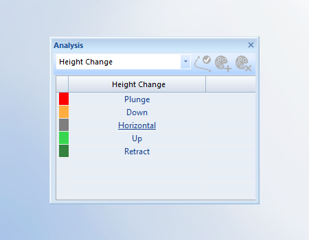
11 toolpath rendering modes that change the color and display of your toolpath. Choose from: Tool Number, Operation number, Operation highlight, Sequence, Linear axis reversal, Orientation change, Segment length, Collisions and proximity, Feed rate, Height change and Single marking.
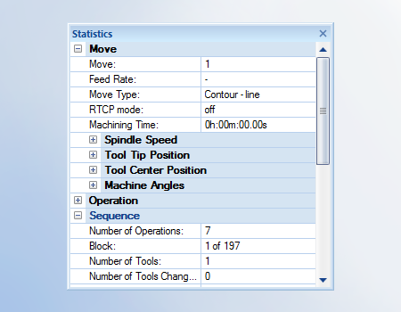
Displays detailed information about your toolpath like: Machining time, Spindle speed, Tool tip position, Tool center position, machining angles and more.
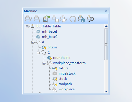
Complete machine definition tree with its components. Interactive and color coded highlight to verify components direction, checking groups and more.
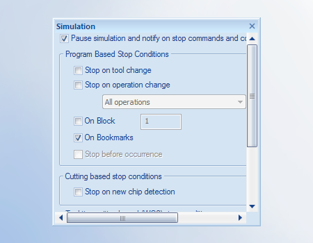
Customize how your simulations with run with options to: Stop on tool change, Stop on operations change, stop on block number and more.
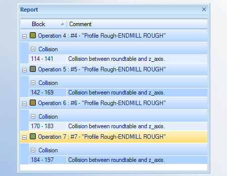
Collision / interference report list collisions that occurred and where they happened.
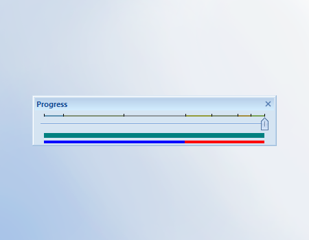
Toolpath slider bar that allows users to fast forward to specific operations. Users can drag the slider bar along to advanced simulation to desired location.
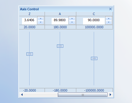
Jog the machines virtual axis to desired locations. Great for verifying limits of machine definition and visualizing the movement of machine components. Drag the slider bar up or down to jog the axis / component, or input a defined value in the input field.
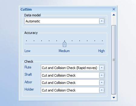
Simulation settings used to adjust quality and checking groups, Save simulation as an STL file or create a section view of stock.
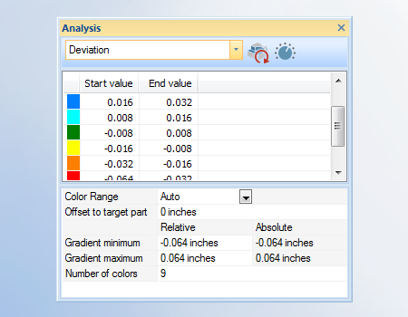
10 simulation rendering modes that change the color and display of machined stock. Choose from None, Tool number, Operation number, Deviation, Height change, Orientation change, Toolpath length, Mark parts, Single marking and gouge and excess.
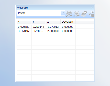
Simulation measuring tools to help you understand the size of your cut models. Choose from points, distances, refine box, remove chips and off.
Restores simulation settings to default, undoing any user customization.
GENERAL


Our solutions enable you and your team to quickly transform new ideas into great products.
Ready To Buy Request for Demo Whatsapp Free Trial Call Us Email Us
Sales: 8427007400 / Email: sales@3dwds.in
Support: 8427007401 / Email: support@3dwds.in
Punjab, Ambala, Delhi, Jammu & Kashmir, Himachal Pradesh
SCF 26, Phase 2, Urban Estate,
Focal Point, Ludhiana - 141010, (Punjab) India